WE RECOMMEND A QUALIFIED TECHNICIAN PERFORM THIS WORK. NO WARRANTY IS
OFFERED ON ELECTRONIC PARTS NOT INSTALLED AND TESTED BY THE FACTORY.
1. DISCONNECT POWER and remove the control box from wall.
2. Remove the existing timer and wire harness. If you had an HP5 Timer, cover the hole with the square plate
furnished.
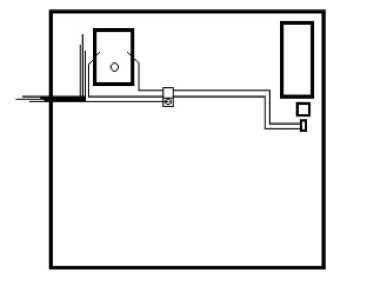
3. Using the template, mark and drill two holes from the back of the box as shown.
4. Mount the timer using the ¼-20 bolt. Use the washer against the timer face. The jamb nut tightens against
the back of the box. DO NOT OVERTIGHTEN.
5. Secure the ground wire to the box using the 8-32 screw. Be sure to route the coin switch wires under the
"P" retainer. See drawing.
6. Using wire nuts, tie all wires together COLOR TO COLOR. NOTE: On older machines, wires were various
colors with blue and green used for the light in the Outside Indicator Box. Connect the old green wire to
the new purple (N.O.) wire from the HRV timer. The black wire in this pair energizes the valve. The blue
wire still connects to timer neutral (#2) as before.
REMEMBER -- THE OLD GREEN WIRE WAS NOT A GROUND.
7. The black and orange wires with the female spade connectors go to the coin switch. The black to the
common (back) spade and the orange to the normally open (middle) spade. The front spade is not used and
may have been cut off.
8. Replace the serial number tape, remount the control box, recheck your work and plug the machine in.
Your machine will now accept up to 250 inputs and can be set to run up to 2 minutes 17 seconds per input.
Web: www.vernonmfg.com Email: steve@vernonmfg.com P: 785.536.4412
Mail & Shipping: 712 Maple Gypsum, KS 67448 Proudly manufactured in the USA